Creating Linkages
Basic Setup
All bike parameters are modified through the Left Sidebar.
Select a Bike to Change
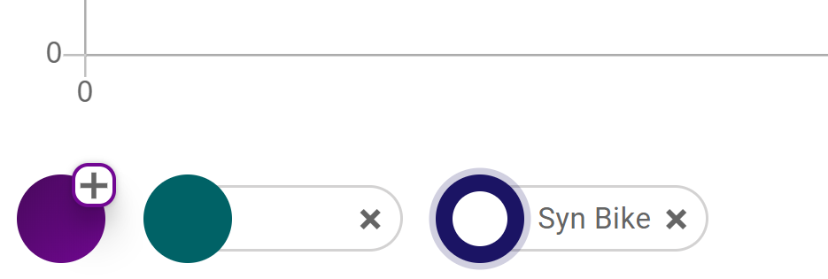
To configure a bikes linkage first select the bike you want to modify by clicking the coloured circle on the bike chip. The selected bikes circle will change to a coloured ring to indicate it is active.
Adjust Critical Geometry
Under the Geometry tab the geo parameters can be set. Several of the parameters are required to set kinematic points.
- Rear Center: Determines the horizontal position of the rear wheel at full extension. Major impact on all kinematics.
- Front Center: Calculated from the bike geometry chart. Will only impact anti-squat and anti-rise results.
- BB Drop: Positions the wheels vertically with respect to the coordinate system. Moderate impact on kinematic results.
- Horz. BB Offset: Is the offset of the bottom bracket with respect to the Global coordinate system (GCS). Rear center is measured from this point impacting the final position of the rear wheel in the GCS.
Setup Linkage Arrangement
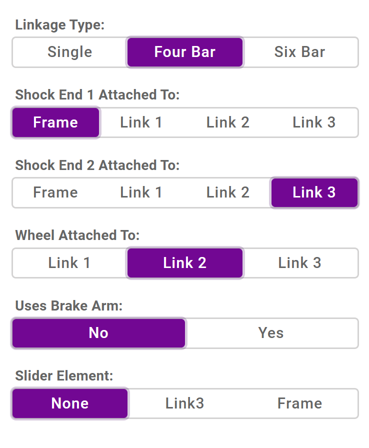
Under the Linkage Setup heading of the Layout tab all the linkage configuration parameters can be adjusted.
The Linkage Type selector determines how many primary links will be in your system. This is not necessarily the same as the common terms for linkages like "Single Pivot". In all cases the frame is counted as the final link.
Once the linkage type is selected the attachments can be made. Non-linkage components such the shock, wheel, and idler can be attached to any member. When changing between linkage types double check all attachments are changed to insure a valid solution.
Adjust Points
Kinematic points can be adjusted by setting values directly on the Kinematic Points heading of the Layout tab or using the graphical plot. To adjust points on the plot either drag the point directly or select the point by clicking it and use the arrow keys to shift the point. The currently selected point will highlighted in light grey. The Q and W keys can be used to tab between the points when the plot is selected
Component Selection
Under the Fork and Shock Info heading the shock stroke and actuation direction are set.
The shock length is controlled through several parameters. Shock Extension Length will normally show the difference between the specified shock length and the two kinematic points defining the ends of the shocks. Instead, it can often be convenient to set the shock length to fixed using the Fix Shock Length selector. This will allow you to adjust either the x or y coordinate at the end of the shock and have the other coordinate update to maintain the exact shock length specified. The shock extension length is set to fixed value in this case.
The Drivetrain Info heading contains the parameters used for calculating anti-squat. Idler pulleys can be enabled here with the Uses Idler selector.
Solving
Normally the plots are updated automatically as you make changes. Live mode can be disabled under the Settings tab which will prevent the plot from updating until the Solve button is pressed. This can be useful if you are running high resolution solves which can increase solve latency and disrupt performance.
Adjust Linkage Graphically
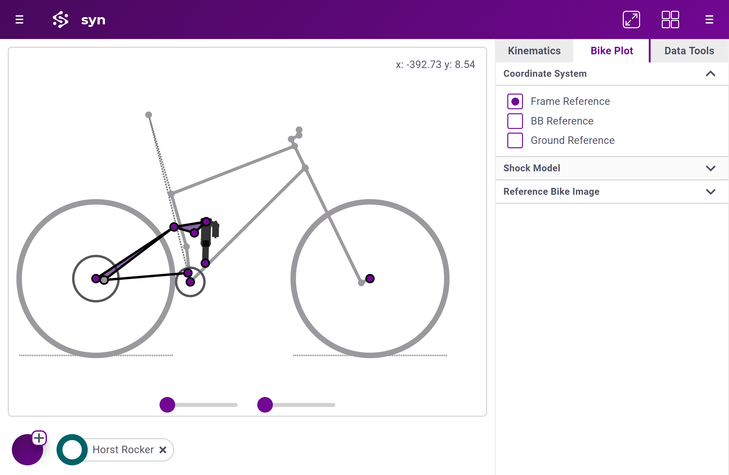
Bike linkages can also be adjust graphically using the Bike Plot which is shown by selecting the Bike Plot tab on the Right Sidebar or by selecting split or stacked plots from the Screen Style selector on the Settings tab.
The linkage can be adjusted by dragging points directly or using the keyboard. Select a point by clicking on it or by using the Q and W key to tab to it. The selected point is highlighted in grey and its current position is shown on the top right corner of the plot. The arrow keys can be used to move the point. Wheel positions can only be set using the geometry parameters.
To see how the linkage acts the Travel Sliders at the bottom of the plot can be used to move the linkage. Selecting different items under the Coordinate System heading of the Bike Plot tab will change how the suspension compression is displayed. This is a visual tool only and does not impact the results. In general most results work in the Ground Coordinate system but Vertical Leverage and the Static results use the Frame Coordinate system.
Model Linkage from an Image
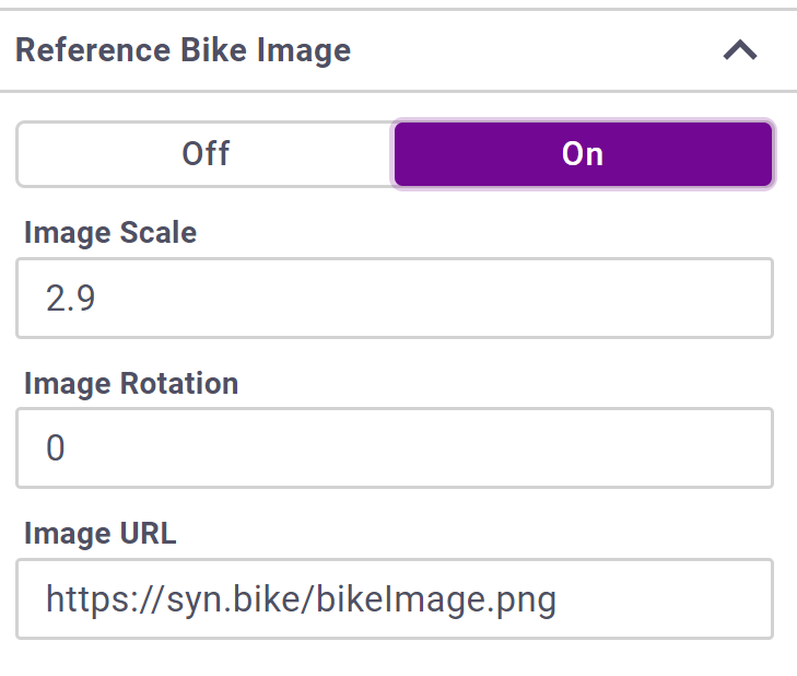
To model a bike from a reference image go to the control found under the Bike Plot tab of the Right Sidebar.
Any image link can be used to load an image into the plot. Scaling and rotation parameters can be set. It is good practice to set the geometry of your frame and then align the image.
Troubleshooting
Syn uses a robust force-based solver with a large amount of flexibility. As a result there is many combinations of parameters that will not lead to a valid solution.
If you are not getting a solution check the following:
- If you have recently changed they type of linkage (such as going from a 4 bar to a single pivot) insure that all of the connections are on links that exist. Changing the linkage type will not move any connections on its own.
- Insure the shock is connected to at least 1 moving link. If the linkage looks correct but is not moving try changing the shock direction (push/pull). It may be that your configuration is driving the shock in the wrong direction.
- Check for linkage lockouts. Moving the Travel Sliders at the bottom will allow you to see where the links might end up reversing. Incorrect connections may cause lockout unintentionally.
Note that if the linkage locks up partially through the travel you will still get plotted curves until there is a lockout or shock reversal. Open the Bike Info panel by clicking on the bikes name to see how much shock travel was able to be used.