Flip Chips and Modifiers
Configuration
Bike modifications such as flip chips, cockpit adjustments, suspension changes can be modelled through the Modify tab of the Left Sidebar.
Unlike creating a new bike model, modifiers use the existing frame and link geometry. A solver engine then resolves the resulting bike geometry and new link positions. This offers instant feedback on how current platforms can be adjusted using new linkages and components.
Select a Chip Configuration
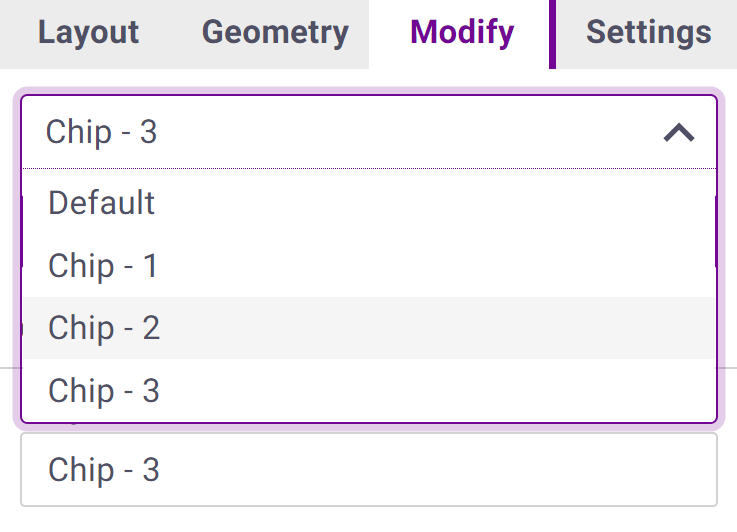
Each chip configuration is composed of a complete set of linkage point-offsets and bike modifiers. Bikes can have multiple chip configurations to store different chip settings or bike setups. A chip can loaded from the Chip Selection dropdown or a new chip can be created by clicking New.
Chip Structure
Chips are composed of both bike modifiers and linkage point-offsets. Every bike will have a Default chip configuration which sets all modifiers to zero and provides the nominal bike configuration.
Geometry modifiers include:
- Fork Length: Adds this amount to the fork length. Useful for determining the impact of long/short forking a bike.
- Fork Offset: Adds this amount to the fork offset.
- Shock Length: Adds this amount to the total shock length (shock length + shock extension length) and moves the linkage to accommodate the change in shock length. This is useful for evaluating the impacts of changing shock extensions and long/short shocking a bike.
- Shock Stroke: Adds this amount to the shock stroke that that the linkage will be solved too. No impact on geometry or point positions.
- Tire Diameters: If set to zero all geometry and kinematics are computed using the stock tire diameter. If the values are non-zero the tire diameter used for solving will be overridden with the value given. Useful for evaluating the impacts of different tire and wheel selections on a platform.
Point modifiers are offsets from stock positions with respect to the original frame coordinate system. This allows associated CAD models to reference a single static coordinate system when laying out flip chip options.
Linkage pivot points can be adjusted on either connecting link with different results for each. As an example with a Horst-link bike moving the CS-SS pivot -10mm in x on the chainstay will lengthen the chainstay link and push the wheel further back. Moving the CS-SS pivot on the seatstay -10mm in x will instead change the seatstay geometry and pull the wheel closer to the bottom bracket. Link attachments such as idlers, wheels, and shock are only adjusted on the link they connect to.
Solving
As with standard bike changes the plots are normally updated automatically as you make changes. Live mode can be disabled under the Settings tab which will prevent the plot from updating until the Solve button is pressed. This can be useful if you are running high resolution solves which can increase solve latency and disrupt performance.
Bike Plot
Chip changes will be reflected in the bike plot. Point offsets will be show with a thick black line. Depending on the reference coordinate system the bike will either be shown with the frame fixed in space or rotated with respect to the wheelbase. Both views can be helpful when reviewing the changes to linkages and bike geometry resulting from a chip configuration. To compare between chips we recommend loading two copies of the same bike and setting each to a different chip configuration.
Geometry Analysis
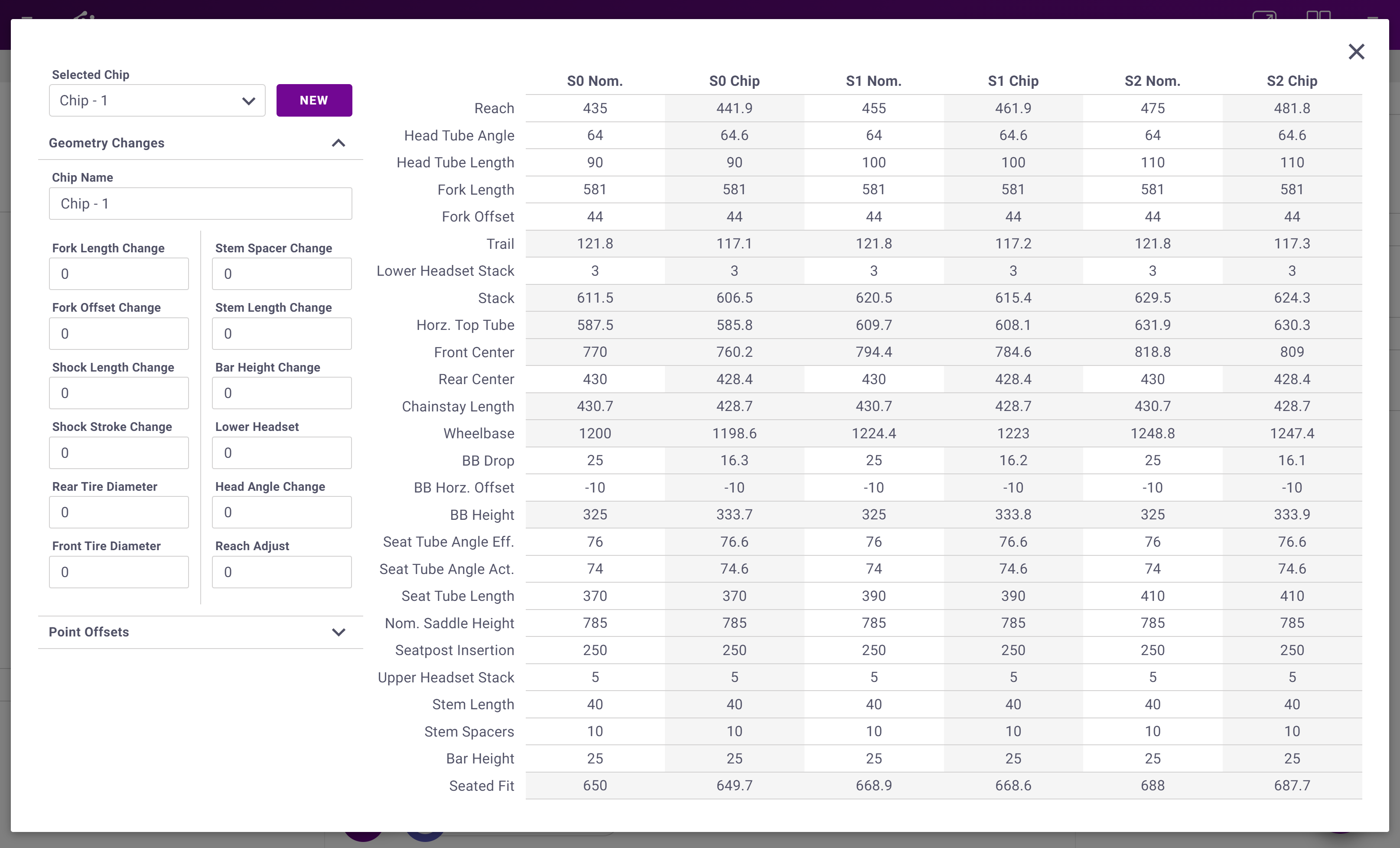
Complete geometry tables for the chip configurations can be viewed by clicking Geo Analysis from the Modify tab. As flip chip configuration parameters are changed the resulting geometry will be updated instantly. The bikes nominal geometry parameters can also be adjusted here identically to the table accessible from the Geometry tab.
Troubleshooting
The flip chip design engine is designed to be as flexible as possible. However many chip configurations are possible that will not lead to a valid result. In general chip displacements in the range of [-10mm, 10mm] are quite safe. Larger displacements and certain linkage types can be more prone to invalid configurations due to linkage locking or inversions.
There are some caveats to the chip design module:
- The resulting linkage must be a valid 2/4/6 bar linkage with the nominal shock length. For example you cannot have a linkage that is locked out or inverted at the stock shock length and rely on the Shock Length change parameter to create a valid solution. For this case you must model the linkage arrangement as a separate bike file.
- Linkage connections cannot be changed. For example you cannot change shock or wheel connection points using chips.
- Slider bikes do not allow movement of the slider rail connections points. Other points can still be chipped.
Note that if the linkage locks up partially through the travel you will still get plotted curves until there is a lockout or shock reversal. Open the Bike Info panel by clicking on the bikes name to see how much shock travel was able to be used.